Phase 3: Commissioning & Integration (C&I)
Before feeding real signal into the DAS, engineers want to make sure that the DAS will work as expected. That means they check ALL the signal paths within the electronics and cables and make sure they are working as expected. This is ensured in the commissioning process.
In this post, we will talk about high level steps of commissioning and Integration.
Initial configuration of electronics:
This confirms visibility of all devices as well as connectivity between them. Integrator makes sure that all the devices connected to the head-end are visible from data controller. Data controller allows you to see all the connected devices.
CW or Continuous Wave Test to check ALL signal paths:
We already checked various qualities of the cable path through Sweep, PIM, OTDR, and Optical Loss Tests during the construction. By doing these we made sure all the cables are ready to transmit signal properly.
We need to check signal paths from head-end to remotes and all the way to antennas. We do that by using CW or Continuous Wave signal. CW signal is basically a blank signal - i.e., it's a signal that does not carry any data. We feed continuous wave signal into the head-end and then measure signal at each electronics on the way to the antennas, we are essentially checking the full signal paths. Now we compare that measured output against the calculated value to determine if the system is working as expected or not. How can we get all the calculated values? We can manually calculate it, but engineers usually can get all the calculated values from iBwave.
Checking for multiple frequencies: If you are building a multi-carrier DAS, engineers will also have to check these paths in multiple frequencies - because electronics may have cards within them dedicated to particular frequencies.
Checking Downlink & Uplink: Engineers will also have to check downlink and uplink paths.
Let's walk through a block diagram (below) that shows all the typical test points during the CW test.
Above is a block diagram of DAS 2.0 system you have seen before. For DL, CW Signal Source output is fed into RIU or RF Interface Unit. Note that for UL, signal source output will be fed into antennas or remotes. Or basically we will start in the opposite end of the DAS. Now we start measuring signals at all the points shown by dotted lines with arrows on the tip.
When we check signal at different locations, and in different frequencies, and in downlink & uplink paths, engineers end up with a lot of data. All of these measured data is compared against the calculated value from the iBwave program. If the DAS is built right, these calculated vs. measured values should be very close.
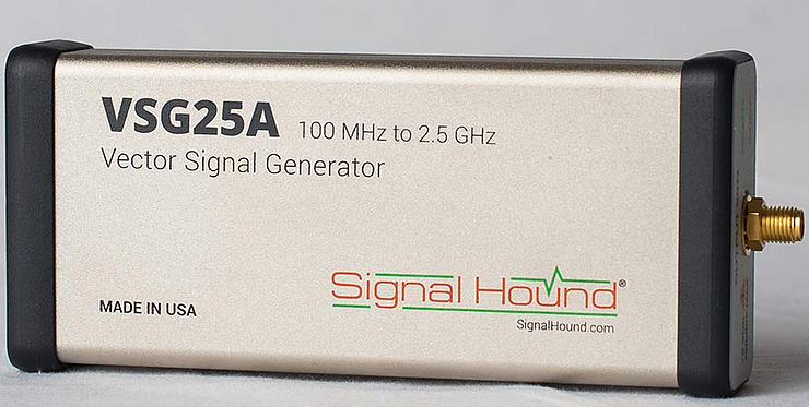
Tools used for CW test are: CW Signal Source (to feed signal) often called Sig Gen or Signal Generator
To measure output, we use Power Meter or Spectrum Analyzer ("Spec A”).
CW Signal Generator (commonly referred to as Sig Gen)
Spectrum Analyzer (Spectrum Master MS2720T)
Integration or adding Carrier Signal Source:
Once the engineers complete all the steps described above, DAS is ready to accept carrier signal - which means Sprint or AT&T or Verizon can now join the DAS.
We are assuming at this point that the intended carriers have installed and turned up their signal source at the site. This installation of carrier signal source can be a whole project by itself but that's not within the scope of this post.
Noise Optimization:
Too much noise can drown the real signal. Noise can be a big problem if not properly optimized.
When we talk about NOISE we are mainly talking about Uplink Noise - the noise that is going back to the signal source.
Sometimes this noise optimization can be done in two phases:
Phase 1 or First phase noise optimization. This Noise optimization happens before the carriers connect their signal source. DAS is optimized by decreasing the noise generated by adding all the DAS electronics.
Phase 2 is the Noise optimization done after adding signal source: DAS engineers will have to do this noise optimization separately with each carrier.
At this point carriers can start collecting signal data to make sure DAS is working as expected – which is part of their Acceptance and Testing Procedure or ATP process.
Related Posts:


